
F A Q
Q5. about Display
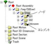
A. Node is equivalent to the file in file system of Windows and it includes lower nodes or elements.
Element approve figure element and is the minimum unit to operate.
A. They are names of display construction of Expressus.
Figure port is the area where the figure can be displayed.
Tree view is the area on the left side where node and element are displayed.
Tool bar
Figure port
Tree view
Contextual menu
Status bar
Pull-down menu
Menu bar
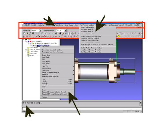
A. It's the menu displayed by the right click on the figure port, or by the right click on the tree view after directing a node element.
Contextual menu is different depends on where to right click.
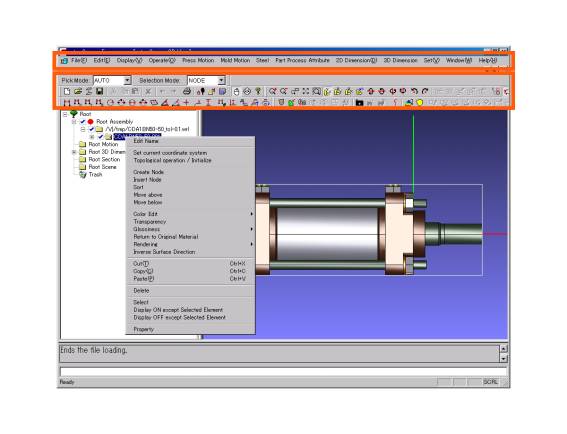
A. Execution of a command is operated there.
A command is executed from the menu bar, the tool bar, and the conxtual menu.
The contextual menu
The tool bar
The menu bar

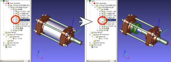
A. It is the operation which check or uncheck in the check box next to a node or an element in the tree view.
Only the parts of the checked node and an element are displayed on the figure port.
Parts will not be displayed by unchecking.
The ON / OFF operation on the node reflects display ON / OFF of a lower node or an element.
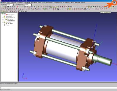
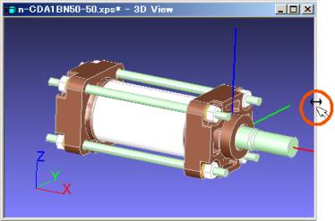
A. When a file is opened by Expressus, it is displayed in 3D port expressed with three dimensions.
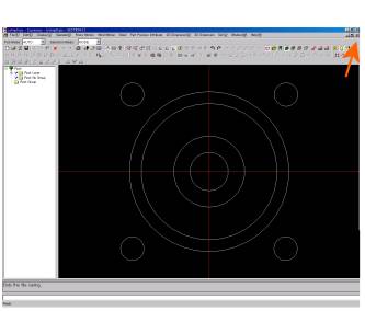
During operation, if a section and a view are created, the figure which expressed by two dimensions is created, and this is called 2D port (or section port).
How to open 2D port
There are 4 ways to open 2D port...
1. Select a section node name in the tree view, and select 'Open Section Port' from 'Operate' in the menu bar.
2. Right click on the section node name, and select 'Open Section Port' in the contextual menu.
3. Select a section node name in the tree view, and click 'Open Section
Port' button ![]() in the tool bar.
in the tool bar.
4. Double click a section node name in the tree view.
A Section name can be changed with the contextual menu by right clicking.
If a section and a view are created, Section nodes (SECTION-1, VIEW_BTM -1, etc.) will be automatically created in the lower rank of the Root Section node in the tree view.
![]()
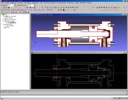
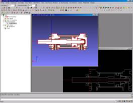
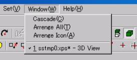
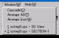
A. Multiple ports can be displayed by selecting 'Cascade' or 'Arrange All' from 'Window' in the menu bar.

'Cascade'
'Arrange All'
A. They can be displayed in piles by clicking the button ![]() at the upper right of a port.
at the upper right of a port.
Drag the end of a port.
The directed port is displayed on the front by clicking the port name.
![]()
A. How to close is different.
There are 2 ways to close the 2D port.
!. Select '3D View' from 'Window' in the menu bar.
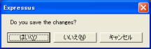
3D port is closed if ![]() button at the upper right of Windows is clicked accidentally.
button at the upper right of Windows is clicked accidentally.
The following message is displayed before closing.
By choosing 'Cancel', you can return to 2D port.
![]()
![]()
How to close the 3D port
1. Select 'Close' from 'File' in the menu bar.
2. Click ![]() button at the upper right of a port
button at the upper right of a port
2. Click ![]() button at the upper right of a port
button at the upper right of a port
2. Click ![]() button at the upper right of Windows.
button at the upper right of Windows.
1. Select 'Exit' from 'File' in the menu bar.
How to exit Expressus
A. There are 3 ways to do viewing operation (pan, tilt and zoom).
>
Set it by 'Configuration' from 'Set' in the menu bar
3. The same operation method as CATIA V5.
1. The operation method by key operation.
2. The same operation method as CADCEUS..


<Pan>
Parallel translation of the display element is carried out in a figure port.
When it becomes pan operation mode, a mouse cursor will change to ![]() .
.
1. Move a mouse with pressing F2 key. (It is not dragging.)
You can also perform parallel translation by a mouse left button dragging.
* Dragging is the operation which moves a mouse with the button of a mouse
pressed.
3. Drag with the center button of a mouse pressed.
<Tilt>
Rotation movement of the display element is carried out in the figure port.
When it becomes tilt operation mode, a mouse cursor will change to ![]() .
.
1. Move a mouse with pressing F1 key. (It is not dragging.)
You can also perform rotation movement by a mouse right button dragging.
![]() key +
key + ![]() key ...rotate centering on +Y axis
key ...rotate centering on +Y axis
![]() key +
key + ![]() key ...rotate centering on -Y axis
key ...rotate centering on -Y axis
![]() key +
key + ![]() key ...rotate centering on -X axis
key ...rotate centering on -X axis
2. ![]() key +
key + ![]() key ...rotate centering on +X axis
key ...rotate centering on +X axis
![]() key +
key + ![]() key ... moves rightward
key ... moves rightward
![]() key +
key + ![]() key ... moves downward
key ... moves downward
![]() key +
key + ![]() key ... moves upward
key ... moves upward
2. ![]() key +
key + ![]() key ... moves leftward
key ... moves leftward
![]() key +
key + ![]() key +
key + ![]() key ...rotate centering on +Z axis
key ...rotate centering on +Z axis
![]() key +
key + ![]() key +
key + ![]() key ...rotate centering on -Z axis
key ...rotate centering on -Z axis
3. Drag with the center button and either left button or right button of a mouse pressed.
<Zoom up /down>
Zoom up and down the display element in the figure port.
When it becomes zoom operation mode, a mouse cursor will change to ![]() .
.
* Wheel is the center button of a mouse and it is called wheel rotation to rotate the wheel forward and backward.
You can zoom up and down by dragging of the center button of a mouse, or by wheel rotation.
1. To zoom up ... Move cursor to above of a screen with pressing F3 key.
To zoom down ... Move cursor to down of a screen with pressing F3 key.
(A motion of the right-and-left direction of a screen is disregarded.)
2. ![]() key +
key + ![]() key ... zoom up
key ... zoom up
![]() key +
key + ![]() key ... zoom down
key ... zoom down
3. Single-click the left button and drag the mouse up and down with pressing the center button of a mouse.
![]()
![]()
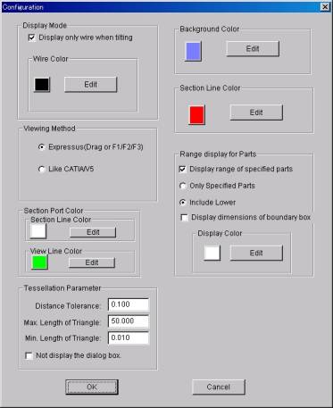
A. Select 'Comfiguration' from 'Set' in the menu bar, and set at the 'Configuration' dialog.
Check the box of 'Display only wire when tilting'.
However, if it restricts to the zoom operation by wheel rotation, even if this check box is checked, it is not displayed by the wire at the time of zoom operation.
In "section display mode", when changing the "wire color",
set it up so that it may not overlap with other background colors, section
line color, etc. with considering the figure displayed.
The size of a port can be changed.